![]()
작성일: 2017.12.03
1. PRBS
- Generator and Receiver
2. E2
- Framer / Deframer (according ITU-T G.703 / G.742)
3. E3
- Framer / Deframer (according ITU-T G.703 / G.751)
4. E3 - Mux / Demux
- Multiplexer of 16 E1 Channels (according ITU-T G.703 / G.742 / G.751)
5. VCO
- Voltage Controlled Oscillator
1. PRBS - Generator and Receiver
The different types of PRBS and the suggested data-rates for the different PRBS types are described in the ITU-T standards O.150, O.151, O.152 and O.153
| PRBS type | Standard | Suggested Datarate [kbit/sec] | Feedback tap |
|---|---|---|---|
| 29 -1 | ITU-T O.150 / O.153 | up to 14.4 | 5th + 9th |
| 211 -1 | ITU-T O.150 / O.152 / O.153 | 64, n*64 (n=1..31), 48 to 168 | 9th + 11th |
| 215 -1 | ITU-T O.150 / O.151 | 1544, 2048, 6312, 8448, 32064, 44736 | 14th + 15th |
| 220 -1 | ITU-T O.150 / O.151 | 1544, 6312, 32064, 44736 | 17th + 20th |
| 220 -1 | ITU-T O.150 / O.153 | up to 72 | 3rd + 20th (note 1) |
| 223 -1 | ITU-T O.150 / O.151 | 34368, 44736, 139264 | 18th + 23rd |
| 229 -1 | ITU-T O.150 | 27th + 29th | |
| 231 -1 | ITU-T O.150 | 28th + 31st |
Documentation for the PRBS-Moduls : PDF-Document
VHDL-Moduls of the PRBS-Generator and Receiver : Zip-File
1.a. PRBS - Generator
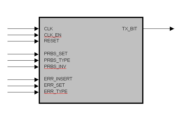
entity PRBS_TX_SER is
  port (
    CLK        : in  std_logic;                      -- synchron clock
    RESET      : in  std_logic;                      -- asynchron reset
    CLK_EN     : in  std_logic;                      -- clock enable
    PRBS_SET   : in  std_logic;                      -- set new PRBS / bit pattern
    PRBS_TYPE  : in  std_logic_vector (3 downto 0);  -- type of PRBS / bit pattern
    PRBS_INV   : in  std_logic;                      -- invert PRBS pattern
    ERR_INSERT : in  std_logic;                      -- manual error insert
    ERR_SET    : in  std_logic;                      -- set new error type
    ERR_TYPE   : in  std_logic_vector (3 downto 0);  -- error type
    TX_BIT     : out std_logic                       -- tx serial output
  );
end PRBS_TX_SER;
1.b. PRBS - Receiver
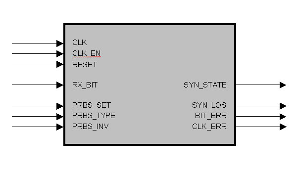
entity PRBS_RX_SER is
  port (
    CLK        : in  std_logic;                      -- synchron clock
    RESET      : in  std_logic;                      -- asynchron reset
    CLK_EN     : in  std_logic;                      -- clock enable
    RX_BIT     : in  std_logic;                      -- rx serial input
    PRBS_SET   : in  std_logic;                      -- set new PRBS / bit pattern
    PRBS_TYPE  : in  std_logic_vector (3 downto 0);  -- type of PRBS / bit pattern
    PRBS_INV   : in  std_logic;                      -- invert PRBS pattern
    SYN_STATE  : out std_logic;                      -- synchronisation state output
    SYN_LOS    : out std_logic;                      -- sync loss signaling output
    BIT_ERR    : out std_logic;                      -- biterror signaling output
    CLK_ERR    : out std_logic                       -- clockerror (bitslip) signaling output
  );
end PRBS_RX_SER;
2. E2 - Framer / Deframer (according ITU-T G.703 / G.742)
Standard : ITU-T G.703 and G.742
Datarate : 8448 kbit/sec
Tolerance : +/- 30 ppM
The E2 transmission scheme according G.742 consists of frames with a length of 848 bits. A frame consists of four sets, which are 212 bits long. 9962.26 frames are transmitted per second.
The nominal data rate of E1 is 2048 kbit/sec. The E2 payload inclusive the justification payload bits can transport per E1 channel 2052.2 kbit/sec. Without the justification payload bits the transport capacity per E1 channel is 2042.3 kbit/sec. The justification payload bits are used to transport data with a utilisation of 57.6 % at the nominal E1 data rate of 2048 kbit/sec.
Documentation for the E2-Framer/Deframer-Moduls : PDF-Document
VHDL-Moduls of the E2-Framer/Deframer-Moduls : On Request
2.a. E2 - Framer
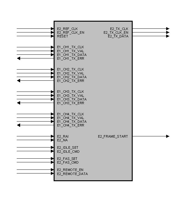
entity E2_G742_FRAMER is
  port (
    E2_REF_CLK     : in  std_logic;                      -- Framer Clock
    E2_REF_CLK_EN  : in  std_logic;                      -- Framer Clock Enable
    RESET          : in  std_logic;                      -- Reset
    E1_CH1_TX_CLK  : in  std_logic;                      -- E1 Channel 1 Clock
    E1_CH1_TX_VAL  : in  std_logic;                      -- E1 Channel 1 Data Valid
    E1_CH1_TX_DATA : in  std_logic;                      -- E1 Channel 1 Data
    E1_CH1_TX_ERR  : out std_logic;                      -- E1 Channel 1 Error-Out
    E1_CH2_TX_CLK  : in  std_logic;                      -- E1 Channel 2 Clock
    E1_CH2_TX_VAL  : in  std_logic;                      -- E1 Channel 2 Data Valid
    E1_CH2_TX_DATA : in  std_logic;                      -- E1 Channel 2 Data
    E1_CH2_TX_ERR  : out std_logic;                      -- E1 Channel 2 Error-Out
    E1_CH3_TX_CLK  : in  std_logic;                      -- E1 Channel 3 Clock
    E1_CH3_TX_VAL  : in  std_logic;                      -- E1 Channel 3 Data Valid
    E1_CH3_TX_DATA : in  std_logic;                      -- E1 Channel 3 Data
    E1_CH3_TX_ERR  : out std_logic;                      -- E1 Channel 3 Error-Out
    E1_CH4_TX_CLK  : in  std_logic;                      -- E1 Channel 4 Clock
    E1_CH4_TX_VAL  : in  std_logic;                      -- E1 Channel 4 Data Valid
    E1_CH4_TX_DATA : in  std_logic;                      -- E1 Channel 4 Data
    E1_CH4_TX_ERR  : out std_logic;                      -- E1 Channel 4 Error-Out
    E2_RAI         : in  std_logic;                      -- Remote Alarm Indication
    E2_NA          : in  std_logic;                      -- National Bit
    E2_FRAME_START : out std_logic;                      -- Frame Pulse
    E2_IDLE_SET    : in  std_logic;                      -- Pulse : new IDLE Command
    E2_IDLE_CMD    : in  std_logic_vector (2 downto 0);  -- IDLE Command
    E2_FAS_SET     : in  std_logic;                      -- Pulse : new FAS Command
    E2_REMOTE_EN   : in  std_logic;                      -- Remote Channel : Enable
    E2_REMOTE_DATA : in  std_logic_vector (3 downto 0);  -- Remote Channel : TX Data
    E2_TX_CLK      : out std_logic;                      -- E2 Output Clock
    E2_TX_CLK_EN   : out std_logic;                      -- E2 Output Clock Enable
    E2_TX_DATA     : out std_logic                       -- E2 Output Data
  );
end E2_G742_FRAMER;
2.b. E2 - Deframer
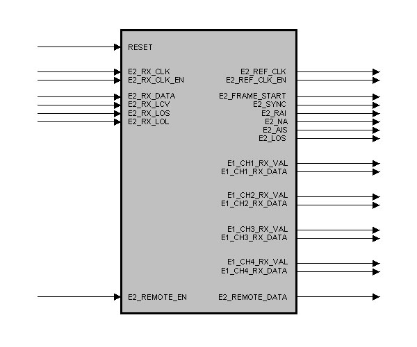
entity E2_G742_DEFRAMER is
  port (
    RESET          : in  std_logic;                      -- Reset
    E2_RX_CLK      : in  std_logic;                      -- RX Input Data Clock
    E2_RX_CLK_EN   : in  std_logic;                      -- RX Input Data Clock Enable
    E2_RX_DATA     : in  std_logic;                      -- RX Input Data
    E2_RX_LCV      : in  std_logic;                      -- RX Code Violation
    E2_RX_LOS      : in  std_logic;                      -- RX Loss Of Signal
    E2_RX_LOL      : in  std_logic;                      -- RX Loss Of Lock
    E2_REF_CLK     : out std_logic;                      -- Output Ref. Clock
    E2_REF_CLK_EN  : out std_logic;                      -- Output Ref. Clock Enable
    E2_FRAME_START : out std_logic;                      -- Frame Pulse
    E2_SYNC        : out std_logic;                      -- State : Frame Synchronous
    E2_RAI         : out std_logic;                      -- State : RAI Bit
    E2_NA          : out std_logic;                      -- State : NA Bit
    E2_AIS         : out std_logic;                      -- State : Alarm Ind. Signal
    E2_LOS         : out std_logic;                      -- State : Loss Of Signal
    E1_CH1_RX_VAL  : out std_logic;                      -- E1 Channel 1 Data Valid
    E1_CH1_RX_DATA : out std_logic;                      -- E1 Channel 1 Data
    E1_CH2_RX_VAL  : out std_logic;                      -- E1 Channel 2 Data Valid
    E1_CH2_RX_DATA : out std_logic;                      -- E1 Channel 2 Data
    E1_CH3_RX_VAL  : out std_logic;                      -- E1 Channel 3 Data Valid
    E1_CH3_RX_DATA : out std_logic;                      -- E1 Channel 3 Data
    E1_CH4_RX_VAL  : out std_logic;                      -- E1 Channel 4 Data Valid
    E1_CH4_RX_DATA : out std_logic;                      -- E1 Channel 4 Data
    E2_REMOTE_EN   : in  std_logic;                      -- Remote Channel : Enable
    E2_REMOTE_DATA : out std_logic_vector (3 downto 0)   -- Remote Channel : RX Data
  );
end E2_G742_DEFRAMER;
3. E3 - Framer / Deframer (according ITU-T G.703 / G.751)
Standard : ITU-T G.703 and G.751
Datarate : 34 368 kbit/sec
Tolerance : +/- 20 ppM
The E3 transmission scheme according G.751 consists of frames with a length of 1536 bits. A frame consists of four sets, which are 384 bits long. 22375 frames are transmitted per second.
The nominal data rate of E2 is 8448 kbit/sec. The E3 payload inclusive the justification payload bits can transport per E2 channel 8457.75 kbit/sec. Without the justification payload bits the transport capacity per E2 channel is 8435.375 kbit/sec. The justification payload bits are used to transport data with a utilisation of 56.4 % at the nominal E2 data rate of 8448 kbit/sec.
Documentation for the E3-Framer/Deframer-Moduls : PDF-Document
VHDL-Moduls of the E3-Framer/Deframer-Moduls : On Request
3.a. E3 - Framer
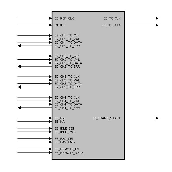
entity E3_G751_FRAMER is
  port (
    E3_REF_CLK     : in  std_logic;                      -- Framer Clock
    RESET          : in  std_logic;                      -- Reset
    E2_CH1_TX_CLK  : in  std_logic;                      -- E2 Channel 1 Clock
    E2_CH1_TX_VAL  : in  std_logic;                      -- E2 Channel 1 Data Valid
    E2_CH1_TX_DATA : in  std_logic;                      -- E2 Channel 1 Data
    E2_CH1_TX_ERR  : out std_logic;                      -- E2 Channel 1 Error-Out
    E2_CH2_TX_CLK  : in  std_logic;                      -- E2 Channel 2 Clock
    E2_CH2_TX_VAL  : in  std_logic;                      -- E2 Channel 2 Data Valid
    E2_CH2_TX_DATA : in  std_logic;                      -- E2 Channel 2 Data
    E2_CH2_TX_ERR  : out std_logic;                      -- E2 Channel 2 Error-Out
    E2_CH3_TX_CLK  : in  std_logic;                      -- E2 Channel 3 Clock
    E2_CH3_TX_VAL  : in  std_logic;                      -- E2 Channel 3 Data Valid
    E2_CH3_TX_DATA : in  std_logic;                      -- E2 Channel 3 Data
    E2_CH3_TX_ERR  : out std_logic;                      -- E2 Channel 3 Error-Out
    E2_CH4_TX_CLK  : in  std_logic;                      -- E2 Channel 4 Clock
    E2_CH4_TX_VAL  : in  std_logic;                      -- E2 Channel 4 Data Valid
    E2_CH4_TX_DATA : in  std_logic;                      -- E2 Channel 4 Data
    E2_CH4_TX_ERR  : out std_logic;                      -- E2 Channel 4 Error-Out
    E3_RAI         : in  std_logic;                      -- Remote Alarm Indication
    E3_NA          : in  std_logic;                      -- National Bit
    E3_FRAME_START : out std_logic;                      -- Frame Pulse
    E3_IDLE_SET    : in  std_logic;                      -- Pulse : new IDLE Command
    E3_IDLE_CMD    : in  std_logic_vector (2 downto 0);  -- IDLE Command
    E3_FAS_SET     : in  std_logic;                      -- Pulse : new FAS Command
    E3_FAS_CMD     : in  std_logic_vector (2 downto 0);  -- FAS Command
    E3_REMOTE_EN   : in  std_logic;                      -- Remote Channel : Enable
    E3_REMOTE_DATA : in  std_logic_vector (3 downto 0);  -- Remote Channel : TX Data
    E3_TX_CLK      : out std_logic;                      -- E2 Output Clock
    E3_TX_DATA     : out std_logic                       -- E3 Output Data
  );
end E3_G751_FRAMER;
3.b. E3 - Deframer
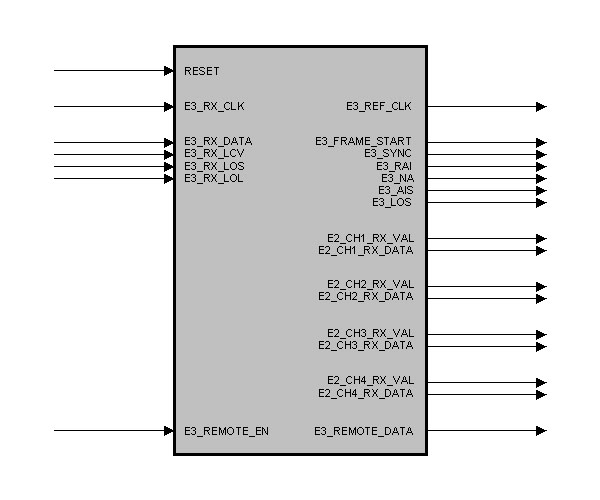
entity E3_G751_DEFRAMER is
  port (
    RESET          : in  std_logic;                      -- Reset
    E3_RX_CLK      : in  std_logic;                      -- RX Input Data Clock
    E3_RX_DATA     : in  std_logic;                      -- RX Input Data
    E3_RX_LCV      : in  std_logic;                      -- RX Code Violation
    E3_RX_LOS      : in  std_logic;                      -- RX Loss Of Signal
    E3_RX_LOL      : in  std_logic;                      -- RX Loss Of Lock
    E3_REF_CLK     : out std_logic;                      -- Output Ref. Clock
    E3_FRAME_START : out std_logic;                      -- Frame Pulse
    E3_SYNC        : out std_logic;                      -- State : Frame Synchronous
    E3_RAI         : out std_logic;                      -- State : RAI Bit
    E3_NA          : out std_logic;                      -- State : NA Bit
    E3_AIS         : out std_logic;                      -- State : Alarm Ind. Signal
    E3_LOS         : out std_logic;                      -- State : Loss Of Signal
    E2_CH1_RX_VAL  : out std_logic;                      -- E2 Channel 1 Data Valid
    E2_CH1_RX_DATA : out std_logic;                      -- E2 Channel 1 Data
    E2_CH2_RX_VAL  : out std_logic;                      -- E2 Channel 2 Data Valid
    E2_CH2_RX_DATA : out std_logic;                      -- E2 Channel 2 Data
    E2_CH3_RX_VAL  : out std_logic;                      -- E2 Channel 3 Data Valid
    E2_CH3_RX_DATA : out std_logic;                      -- E2 Channel 3 Data
    E2_CH4_RX_VAL  : out std_logic;                      -- E2 Channel 4 Data Valid
    E2_CH4_RX_DATA : out std_logic;                      -- E2 Channel 4 Data
    E3_REMOTE_EN   : in  std_logic;                      -- Remote Channel : Enable
    E3_REMOTE_DATA : out std_logic_vector (3 downto 0)   -- Remote Channel : RX Data
  );
end E3_G751_DEFRAMER;
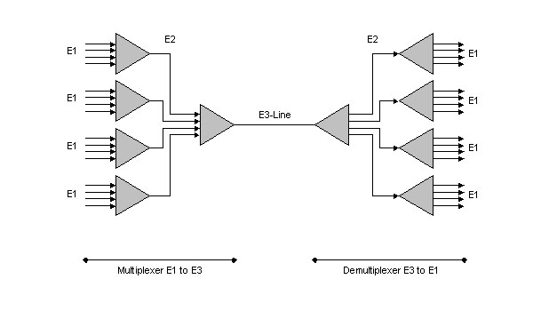
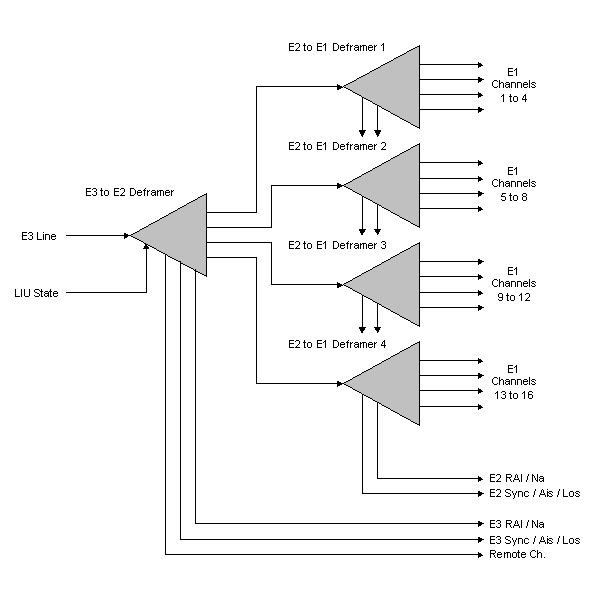
4. E3 - Mux / Demux - Multiplexer of 16 E1 Channels
For transmitting many E1 channels over one line, the ITU describes in the standard G.742 a method for multiplexing four E1 channels to one E2 channel and in the standard G.751 a method for multiplexing four E2 channels to one E3 channel. The used technique is Time Division Multiplexing (TDM).
The multiplexing/demultiplexing is done in two stages :
- First from E1 to E2
- Second from E2 to E3
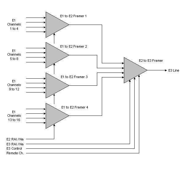
The sixteen E1 input interfaces can be used fully asynchronous compared to the E3 reference clock and the other E1 input clocks. The individual clock enable input for any E1 input interface enables the possibility of working with a higher interface clock rate (like 34.368 MHz). The whole clock-system can be sourced with only one clock too. This is often useful in a greater system.
The Remote Alarm Indication (RAI) and the National Bit (Na) of the E3 frame and the four incorporated E2 frames can be used fully independent of each other.
The generation of the internally needed E2 clock (8448 kHz) is done internally by a special division stage from the E3 reference clock (34.368 MHz).
It's possible to transmit idle-0 or idle-1 in the E3 payload.
It's also possible to transmit an unframed 0 or 1 level.
For testing purposes it's possible to transmit defective Frame Alignment Signals (FAS) to check the counterpart deframer.
An extra data channel in the overhead bits of the E3 frame enables the possibility to transmit user or control data with a data rate of nearly 90 kbit/sec. This feature is fully compliant with the ITU standards. In detail it uses the first four justification control bits (CJ1, J=1..4) in the E3 frame overhead. This is possible because the receiver performs a majority-decision with the three justification control nibbles (CJ1,CJ2,CJ3, J=1..4) when deciding if a justification must be done or not. One erroneous nibble doesn't affect the justification decision.
Combined error outputs for the E1 and the E2 domain reports problems with the signal clocking. If a E1 interface clock is too fast or too slow compared with the E3 reference clock, the E1 interface data are delivered too fast or too slow. This causes a FIFO overflow or an underflow. This event is reported on the combined error output.
Documentation for the E3 - Mux / Demux : PDF-Document
VHDL-Moduls of the E3 - Mux / Demux : Zip-File
4.a. E3 - Multiplexer
4.b. E3 - Demultiplexer
5. VCO - Voltage Controlled Oscillator
This VHDL-Module is a simple VCO. It is only for simulation, not for synthesis.
It is controlled by the following generic values :
VCO_MIN_FREQ : minimal oscillation frequency of the VCO
VCO_MAX_FREQ : maximal oscillation frequency of the VCO
VCO_BEG_FREQ : starting frequency of the VCO at start of simulation (time=0)
DAMPING : damping factor from the Phase Comparator to the VCO-Control-Level
This value controls the rapidness of the VCO frequency change, when the input signals changes.
VHDL-Modul of the VCO-Modul : Zip-File
entity VCO_WITH_PLL is
  generic (
    VCO_MIN_FREQ  : real :=   1000000.0;  -- VCO Minimum Frequency [Hz]
    VCO_MAX_FREQ  : real := 100000000.0;  -- VCO Maximum Frequency [Hz]
    VCO_BEG_FREQ  : real :=  10000000.0;  -- VCO Start Frequency at time = 0 [Hz]
    DAMPING       : real :=       0.001   -- Damping Factor from Phase Comparator to VCO
  );
  port (
    CLK_REF_IN    : in  std_logic;  -- Reference Clock Input
    CLK_FB_IN     : in  std_logic;  -- Reference Clock Input
    CLK_VCO_OUT   : out std_logic   -- Output Clock of the VCO
  );
end VCO_WITH_PLL;
Contact - Information
Thorsten Gaertner
Schulstrasse 10
22113 Oststeinbek
GERMANY
e-Mail : vhdl_at_thorsten-gaertner_dot_de
(Replace "_at_" with "@" and "_dot_" with ".")
출처: http://www.thorsten-gaertner.de/vhdl/vhdl.htm
![]()
![]() Send to a colleague |
Send to a colleague |
![]() Print this document
Print this document